Fluke 732C and 734C DC Voltage Reference Standards
The most accurate and stable 10 V reference in your lab With the 734C, it is remarkably simple to establish and maintain a primary voltage standard in your laboratory. Over time, with frequent intercomparisons of your four units, and regular calibratio
The simple way to maintain and disseminate the volt
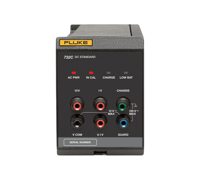
The Fluke Calibration 732C DC Voltage Reference Standard is a RoHS compliant direct voltage reference used to maintain the volt in primary and secondary standards laboratories. Individual 732C voltage standards provide 10 V, 1 V, and 0.1 V outputs and may be transported easily to remote locations while the dc reference is maintained in the laboratory. The 734C DC Voltage Reference Standard consists of four electrically and mechanically independent 732C DC Reference Standards and a rack-width enclosure. Two model families, Base and Select, differ in that the Select models are two times more stable than the Base models.
Because each 732C in the 734C DC Reference Standard is based on the same architecture pioneered in the popular 732A DC Voltage Standard—the first standards lab quality 10 V electronic reference—you can rely on it to provide the same high stability and predictable drift rate you’ve come to expect, in a smaller, more portable package identical to the 732B DC Voltage Standard. The 734C is also compatible with 732B DC standards and can support any combination of 732 B and C models. Similarly, 734A can be used with the newer 732C voltage standards, providing the ultimate flexibility and maximizing asset utilization.
To simplify support of your 734C, Fluke Calibration offers a variety of calibration services to assign values and predicted performance for each of the 10 V outputs, traceable to national standards and to the Fluke Calibration 10 V Josephson Array.
The most accurate and stable 10 V reference in your lab
With the 734C, it is remarkably simple to establish and maintain a primary voltage standard in your laboratory. Over time, with frequent intercomparisons of your four units, and regular calibrations of one or more units, you can reduce the uncertainty of your 734C by a factor of three.
From 1984 until the acquisition of our Josephson Array, the Fluke Calibration Primary Standards Laboratory maintained its corporate volt in this manner, reducing the absolute uncertainty to ± 0.35 μV/V traceable to national standards.
The 734C supports 1 V and 0.1 V
The 1 V and 0.1 V are key calibration / verification points for digital multimeters. Thanks to the high-precision thin-film resistive networks, which are manufactured in Fluke’s own thin-film fab facility, the 734C now comes standard with those two additional outputs. It eliminates the need for external dividers, making the measurement setup easier and less prone to errors.
Choice of Select models for demanding applications
Fluke Calibration offers Select models for customers requiring primary standards lab capability for calibrating demanding workloads and gaining independence from sending standards to other labs for calibration. The process of calibration is the same for both the Base and the Select models. The only exception is that the Select models (732C/S/C or 734C/S/04) are compared to Fluke Calibration J-array for 180 days of drift characterization data and provide two times better stability at 10 V. This process ensures the selection of the best possible standards meeting stringent drift performance requirements.
Supporting your traceability requirements
Fluke Calibration provides the products and services you need to manage your traceability requirements. Fluke Calibration performs an output voltage calibration on a new 732C by comparing it against its own J-array maintained at the factory. The base model 732C is shipped COLD (“not powered”) and comes with a voided calibration certificate demonstrating its operability. The owner is responsible for providing traceability as required locally.
Accredited calibration and drift characterization data comes standard with 732C units ordered to ship “HOT” (powered on). During manufacturing, each 732C is compared to Fluke Calibration direct voltage standards for at least 90 days to obtain the drift characterization data. Once the drift rate is known, the 12-month projected output voltage is determined. The units are then shipped under power. The continuous power-on condition is required during shipment through delivery to your lab for the calibration to remain valid. If continuous power is not maintained, then the validity of the calibration may be compromised. Contact your Fluke Calibration representative to determine if the 732C alternatives are available in your area.
Why a four-unit reference?
A four-unit voltage reference standard is desirable any time you need to maintain and disseminate a reference voltage. At a minimum, three units are intercompared to detect and identify changes in the output of any one cell. A fourth unit may be used as a spare or to transport the volt to or from remote locations. When it returns to the laboratory, it can be compared to the other three to determine if its output has shifted during transport.
However, there is more to a four-unit reference. According to NBS Technical Note 1239, published by the U.S. National Bureau of Standards (now NIST) in 1987, four to six references are required to provide measurement integrity and redundancy, and to minimize the number of measurements required. References must be completely independent of one another. Otherwise, common elements, such as a power supply or oven, might affect the correlation of reference outputs. In addition, with frequent intercomparisons of four units, you can detect when any one of the units begins to drift beyond specifications or needs to be repaired.
Each 732C is a stand-alone dc standard with its own power supply, oven, supporting electronics and packaging. Each may be purchased separately, or as a full 734C system, which includes four 732Cs that slide into a rack-width enclosure.
Why should you prefer the 732C or 734C?
- Independence. The 734C is the only standard of its type offering complete mechanical and electrical independence of each of its four standards.
- Portability. Each 732C Standard is designed for portability. Each is small, light, rugged and has a long operating battery life.
- Confidence. The 732C is based on the proven technology of the Fluke Calibration 732A and 732B. The 732A was the first standards lab quality electronic reference to gain wide acceptance as a replacement for saturated standard cells. Originally designed for internal transfers of Fluke’s corporate volt to the production floor, thousands are now in service worldwide in a variety of applications—from maintaining an institutional reference to transferring values from national labs or privately-operated 10 V Josephson Arrays.
Ideal support for Artifact Calibration
Combined with 742A-1 and 742A-10k Resistance Standards, a single 732C makes a robust and compact Artifact Calibration support package for instruments such as the Fluke 5730A High Performance Multifunction Calibrator and Fluke 8508A Reference Mulitmeters, including the older generation 5700A and 5720A models.
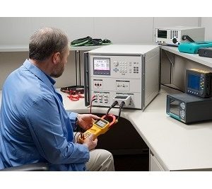
Taking your reference to the workload
Standards laboratory operations have changed. In the past, people brought their workload to the standards lab. Today, the functions of the standards lab are being distributed, requiring that many calibrations be performed in the field. The 734C, and its electrically and mechanically independent 732C Standards, are designed to meet that need. The voltage reference remains undisturbed in your laboratory, while at the same time you can distribute the volt to remote locations outside the lab. When the unit is returned to the lab, comparisons can be made to the reference to determine if a shift has occured during the transfer. To maintain traceability to national standards, one unit may be transported to a national lab or other primary standards lab for calibration, again, without disturbing the reference. Each 732C Standard is relatively light, weighing just 5.9 kg, and its 72-hour battery life provides ample capacity for long shipments. An optional external battery extends that capacity to 210 hours. A special transit case, designed to hold one 732C and an external battery, simplifies transport even further.
The 732C can stand up to a lot of abuse. The outputs can be shorted indefinitely and the 10 V output is protected up to 1100 V dc, 25 mA, without damaging the unit or affecting its output.
Service options from Fluke
Fluke provides two service options: For existing Fluke 732As, 732Bs or 732Cs or similar dc reference standards that are already in use, the Direct Voltage Maintenance Program is a service where Fluke Calibration can provide calibration certificates for these standards. This service consists of two calibration alternatives that can be used depending on your needs.
Calibrations done by Minerva
Calibration certificate services can be easily performed on voltage referrence standards returned to Minerva. Contact us for details regarding these calibration certificate alternatives: Send us an e-mail Sales@minerva-calibration.com or give us a call +31 33 46 22 000.
Calibration in your laboratory
With the Direct Voltage Maintenance Program (DVMP) 732C-200 services, a voltage reference standard owned and calibrated by Fluke Calibration, including all necessary connecting cables and operating instructions, is sent to your site for comparison with one or more of your own reference standards. You make a series of readings over several days and forward the standard to the Fluke Calibration Standards Laboratory. A value for your reference relative to the Fluke standard is assigned. Within one week, a preliminary Report of Calibration is returned to you. Once the standard is returned to Fluke Calibration, it is compared to the Fluke Voltage Reference Standard. A final value is assigned to your reference, and a final Report of Calibration is sent to you. The 732C-200 service provides a calibration certificate for one local standard.
General Specifications
Mains
Line voltage is accepted as shown in Table 1. AC line current at 120V ac is typically 0.13A. Table 1. Mains
| 732C Line Voltage Setting | Line Voltage Accepted | Frequency Accepted |
|---|---|---|
| 100 V | 90 V to 110 V | 50 Hz/60 Hz |
| 120 V | 108 V to 132 V | 50 Hz/60 Hz |
| 220 V | 198 V to 242 V | 50 Hz/60 Hz |
| 240 V | 216 V to 264 V | 50 Hz/60 Hz |
| Battery | Battery Operation | At full charge, the internal battery operates the Product for a minimum of 72hours at 23±5 °C, with 0 mA to 0.1 mA total current drain at the outputs. |
| Charging Time | <36 hours with self-contained automatic battery charger | |
| External DC Input | Rear-panel input for external 12 V dc to 15 V dc powers the Product indefinitely. The dc source must be rated ≥300 mA. | |
| Isolation | Resistance from any of the Product binding posts to earth (chassis) ground or to ac line power is >10 000 MΩ shunted by <1000 pF. | |
| Guard and Ground Terminals | Chassis ground connections are provided on both the front and rear panels. Access to the internal guard is provided by a front-panel binding post. | |
| Output Protection | All outputs can be shorted indefinitely without damage to the Product. The 10 V output can withstand voltages from other sources as follows:
|
|
| Environmental | |
|---|---|
| Specified Operation | Temperature Range: 15 °C to 35 °C |
| Relative Humidity: 0% to 90% to 28 °C, to 80% to 35 °C, and to 50% to 50 °C, Noncondensing | |
| Altitude: 0 m to 1830 m (0 ft to 6000 ft) | |
| Non-specified Operation | Temperature Range: 0 °C to 50 °C |
| Relative Humidity: 0% to 90% Noncondensing | |
| Altitude: 0 m to 3050 m (0ft to 10 000ft) | |
| Storage (Battery Removed) | Temperature Range: -40 °C to 50 °C |
| Relative Humidity: Noncondensing | |
| Altitude: 0m to 12 200 m (0 ft to 40 000 ft) | |
| Electromagnetic Compatibility | |
|---|---|
|
(EMC) The Product operates in Standards Laboratory environments where the radio frequency (RF) environment is highly controlled. |
|
| International |
IEC 61326-2-1; CISPR 11: Group 1, Class A Controlled Electromagnetic Environment Group 1 equipment has intentionally generated and/or use conductively coupled radio-frequency energy which is necessary for the internal functioning of the equipment itself. Class A equipment is equipment suitable for use in all establishments other than domestic and those directly connected to a low voltage power supply network which supplies buildings used for domestic purposes. Emissions which exceed the levels required by CISPR 11 can occur when the equipment is connected to a test object. The equipment may not meet the immunity requirements of 61326-1 when test leads and/or test probes are connected. |
| USA (FCC) | 47 CFR 15 subpart B, this product is considered an exempt device per clause 15.103 |
| Korea (KCC) |
Class A Equipment (Industrial Broadcasting & Communication Equipment) This product meets requirements for industrial (Class A) electromagnetic wave equipment and the seller or user should take notice of it. This equipment is intended for use in business environments and not to be used in homes. |
| Safety | |
|---|---|
| Safety | IEC 61010-1, Installation Category II, Pollution degree 2 |
| Ingress Protection | IEC 60529: IP20 |
| Mechanical Specifications | ||
|---|---|---|
| 734C Dimensions | 732C and 732C-7001 Dimensions | |
| Height | 17.8 cm (7.0 in) | 13.4 cm (5.28 in) |
| Width | 43.2 cm (17.0 in) | 9.8 cm (3.85 in) |
| Depth | 50.3 cm (19.8 in) including handles | 40.6 cm (16.0 in) |
| Weight | 30.4 kg (67 lb) | 5.91 kg (13 lb) |
Performance Specifications
Output Voltages
10 V, 1 V, and 0.1 V are provided at separate binding posts referenced to the VCOM binding post.
Stability
Stability for the 732C outputs at Tcal ±1 °C and IN CAL indicator on is specified in Table 2.
Table 2. Standard Stability
| Output Voltage | Stability (± µV/V) | ||
| 30 Days | 90 Days | 1 Year | |
| 10 V | 0.3 | 0.8 | 2.0 |
| 1 V | 0.6 | 1.2 | 3.0 |
| 0.1 V | 1.2 | 2.9 | 9.8 |
Table 3. Select Stability
| Output Voltage | Stability (± µV/V) | ||
|---|---|---|---|
| 30 Days | 90 Days | 1 Year | |
| 10 V | 0.3 | 0.8 | 1.0 |
| 1 V | 0.6 | 1.2 | 2.5 |
| 0.1 V | 1.2 | 2.9 | 8.0 |
Noise at the Output Terminals
Output noise is specified for both day-to-day observations and for short-term observations, at k=1.
Table 4. Noise at the Output Terminals
| Output Voltage | S1 (±µV/V) [1] | Sra (±µV/V) [2] | Noise (0.01 Hz to 10 Hz) (±µV/V rms) |
|---|---|---|---|
| 10V | 0.07 | 0.05 | 0.06 |
| 1 V | 0.16 | 0.14 | 0.15 |
| 0.1V | 1.4 | 1.3 | 1.0 |
| [1] S1 is the standard deviation about the regression (SDEV) of 90 days of at least twice daily stability test data. [2] Sra is the SDEV of the stability test data with a 7-day moving average filter (MAF). | |||
To obtain the best performance, use the Product in controlled environments with good system grounding and shielding practices. For radiated EMI fields from 0.25 to 1 V/m from 80 to 130 MHz, add 9 µV to the 1 V output, and 3.6 µV to the 0.1 V output. For ac mains conducted EMI of 1 Vrms from 75 to 80 MHz, add 1 µV to the 1 V output, and 0.7 µV to the 0.1 V output. The 10 V output is mostly unaffected by EMI fields up to 1 V/m or by conducted EMI up to 1 Vrms.
Output Current and Impedance
Table 5. Output Current and Impedance
| Output Voltage | Output Current Limit | Output Impedance |
|---|---|---|
| 10V | 12mA [1] | ≤1mΩ |
| 1V | 1.2mA [1] | ≤1mΩ |
| 100mV | 20pA | ≤100Ω |
| [1] Limit total output current to £0.1mA to realize specified battery operation | ||
Retrace (Hysteresis) Error
Table 6 shows the change in 10V output voltage following a power outage (with the battery turned off) and temperature held constant in a 23 °C to 35 °C range.
Table 6. Retrace (Hysteresis) Error
| Period that Power is Turned Off | Change in 10 V Output Value (±µV/V) |
|---|---|
| ≤10min | 0.1 |
| 10min to 24hr | 0.25 |
| 24hr to 14days | 0.25 |
Stabilization Time Requirements
Warmup times required after ac line and battery power have been turned off. The IN CAL indicator will be off, and recalibration will be necessary. The previously-specified retrace error specification can be used in the case of power interruptions.
| With no power interruption | No stabilization time is required after the Product is moved to another environment. |
| Power off for <1 hr | 1-hr warmup required |
| Power off for >1 hr | 24-hr warmup required |
Temperature Coefficient (TC) of Output
From 15 °C to 35 °C, the temperature coefficient is bound by the information in Table 7.
Table 7. Temperature Coefficient
| Output Voltage | Temperature Coefficient (±µV per V/°C) |
|---|---|
| 10 V | 0.04 |
| 1 V | 0.1 |
| 0.1 V | 0.2 |
Output Change with Altitude
For an altitude change from calibration altitude, the output voltage change is bound by the information in Table 8.
Table 8. Output with Altitude
| Output Voltage | Output Change (±µV/V per 1000ft) |
|---|---|
| 10 V | 0.05 |
| 1 V | 0.09 |
| 0.1 V | 0.18 |
Load Regulation
| 10V Output Load Change | Maximum 10V Output Change (±mV/V) |
| 0 mA to 12 mA (no load to full load) | 1 |
| 0 mA to 2 mA | 0.1 |
Line Regulation
The outputs will change no more than 0.05 µV/V for any 10% line voltage change or for the entire operating range of the battery.
| Accessory | Description |
|---|---|
| 732C-7001 |
External Battery and Charger |
| 732C-7002 |
Transit Case, for qty. 1 or 2 732Bs or 732Cs |
| 734C-7001 |
Instrument Enclosure |
| Y734 |
Rack-Mount Kit for 734A or 734A-7001 |
Request a quote - Shop
Gerelateerde producten