290 Series Waveform Generators
These universal waveform generators combine many generators in one instrument.
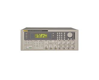
1, 2, or 4 channel 100 MS/s waveform generators
- 100 MS/s 12-bit arbitrary waveform capability
- 1 M point waveform memory
- 40 MHz function generator capabilities using DDS (50 MHz for square waves)
- 10 ns pulse pattern generator
- Waveform sequencing with up to 1024 segments
- Unlimited waveform storage using CF® memory card
- Waveform Manager Plus for Windows software
- USB interface in addition to RS-232 and GPIB
These universal waveform generators combine many generators in one instrument. Their extensive signal simulation capabilities include arbitrary waveforms, function generator, pulse/pulse train generator, sweep generator, trigger generator, tone generator, and amplitude modulation source.
The 290 series uses Direct Digital Synthesis techniques as well as variable clock sampling technology to provide a fully featured programmable function and arbitrary waveform capability.
The 291, 292 and 294 are 100 MS/s arbitrary waveform generators designed to handle real world requirements by test experts. These models can easily simulate complex signals while being easy to use, compact and affordable. On multi-channel units each channel can be operated fully independently, or multiple channels can be linked using simple or complex relationships.
Waveform Manager Plus software provides all the features needed for creation, manipulation and management of arbitrary waveforms within a single Windows based program.
Arbitrary Waveforms |
|
| Waveforms | The maximum arbitrary waveform size is 1 M points. Up to 500 user-defined waveforms may be stored on the removable memory card. Arbitrary waveforms can be defined by front panel editing controls, by downloading of waveform data via RS-232,USB or GPIB, or by writing directly to the removable memory card using the USB card reader/writer connected to a PC. |
| Waveform memory | 1 M points. Minimum waveform size is 8 points. |
| Vertical resolution | 12 bits |
| Sample clock range | 100 mHz to 100 MHz |
| Resolution | 4 digits |
| Accuracy | ± 1 digit of setting |
| Output filter | Selectable between 40 MHz Elliptic, 20 MHz Bessel or none |
| Sequence | Up to 1024 waveforms may be linked. Each waveform can have a loop count of up to 32,768. A sequence of waveforms can be looped up to 1,048,575 times or run continuously. |
| Noise function | Digital noise generated by a 35-bit linear feedback register clocked at 100 MHz. User’s external filter defines bandwidth and response |
Standard Waveforms |
|
| Waveforms | Sine, square, triangle, DC, positive ramp, negative ramp, sin(x)/x, pulse, pulse train, cosine, haversine and havercosine |
Sine, Cosine, Haversine, Havercosine |
|
| Range | 0.1 mHz to 40 MHz |
| Resolution | 0.1 mHz or 10 digits |
| Accuracy | Better than 10 ppm for 1 year |
| Temperature stability | Typically < 1 ppm/°C |
| Output level | 5 mV to 20 V p-p from 50 Ω |
| Harmonic distortion | < 0.15 % THD to 100 kHz; < –60 dBc to 20 kHz, < –50 dBc to 1 MHz, < –40 dBc to 10 MHz, < –30 dBc to 40 MHz |
| Non-harmonic spurii | < –60 dBc to 1 MHz, < –60 dBc + 6 dB/octave 1 MHz to 40 MHz |
Square |
|
| Range | 1 mHz to 50 MHz |
| Resolution | 1 mHz (4 digits) |
| Accuracy | ± 1 digit of setting |
| Output level | 5 mV to 20 V p-p from 50 Ω |
| Rise and fall times | < 8 ns |
Triangle |
|
| Range | 0.1 mHz to 500 kHz |
| Resolution | 0.1 mHz or 10 digits |
| Accuracy | Better than 10 ppm for 1 year |
| Output level | 5 mV to 20 V p-p from 50 Ω, linearity error: < 0.1 % to 30 kHz |
Ramps and Sin(x)/x |
|
| Range | 0.1 mHz to 500 kHz |
| Resolution | 0.1 mHz or 10 digits |
| Accuracy | Better than 10 ppm for 1 year |
| Output level | 5 mV to 20 V p-p from 50 Ω |
| Linearity error | < 0.1 % to 30 kHz |
Pulse and Pulse Train |
|
| Output level | 5 mV to 20 V p-p from 50 Ω |
| Rise and fall times | < 8 ns |
| Period | Range: 40 ns to 100 s; Resolution: 4-digits; Accuracy: ± 1 digit of setting |
| Delay | Range: –99.9 s to + 99.99 s; Resolution: 0.001 % of period or 10 ns |
| Width | Range: 10 ns to 99.99 s; Resolution: 0.001 % of period or 10 ns |
Trains of up to 10 pulses may be specified, each having independently defined width, delay and level. The baseline voltage is separately defined and the sequence repetition rate is set by the pulse train period.
Operating Modes |
|
| Continuous | Waveform runs continuously |
| Triggered Burst | Each active edge of the trigger signal will produce one burst of the waveform |
| Carrier waveforms | All standard and arbitrary |
| Max. carrier frequency | The smaller of 2.5 MHz or the maximum for the selected waveform. 100 Msamples/s for ARB or Sequence. |
| Number of Cycles | 1 to 1048575 |
| Trigger rep. rate | 0.005 Hz to 100 kHz internal, dc to 1 MHz external |
| Trigger source | Internal from keyboard or trigger generator. External from TRIG IN or remote interface. |
| Start/stop phase | ± 360 ° settable with 0.1 ° resolution, subject to waveform frequency and type |
| Gated | Waveform will run while the Gate signal is true and stop while false |
| Carrier waveforms | All standard and arbitrary |
| Max. carrier frequency | The smaller of 2.5 MHz or the maximum for the selected waveform. 80 Msamples/s for ARB or Sequence. |
| Trigger rate | 0.005 Hz to 100 kHz internal, dc to 1 MHz external |
| Gate signal source | Internal from keyboard or trigger generator. External from TRIG IN or remote interface. |
| Start/stop phase | ± 360 ° settable with 0.1 ° resolution, subject to waveform frequency and type |
| Sweep | Capability provided for both standard and arbitrary waveforms. Arbitrary waveforms are expanded or condensed to exactly 4096 points and DDS techniques are used to perform the sweep. |
| Carrier waveforms | All standard and arbitrary except pulse, pulse train and sequence. Sweep mode: Linear or logarithmic, continuous or triggered. |
| Sweep direction | Up, down, up/down or down/up |
| Sweep range | 1 mHz to 40 MHz in one range. Phase continuous. Independent setting of start/stop frequency. |
| Sweep time | 1 ms to 999 s (3 digit resolution) |
| Marker | Variable during sweep. |
| Sweep trig. Source | The sweep may be free run or triggered from the following sources: Manually from keyboard. Externally from TRIG IN input or remote interface. |
| Sweep hold | Sweep can be held and restarted by HOLD key |
| Tone Switching | Capability provided for both standard and arbitrary waveforms. Arbitrary waveforms are expanded or condensed to exactly 4096 points and DDS techniques used to allow instantaneous frequency switching. |
| Carrier waveforms | All waveforms bar pulse, pulse train, sequence |
| Frequency list | Up to 16 frequencies from 1 mHz to 40 MHz |
| Trigger rep. rate | 0.005 Hz to 100 kHz internal, dc to 1 MHz external. Usable repetition rate and waveform frequency depend on the tone switching mode. |
| Source | Internal from keyboard or trigger generator. External from TRIG IN or remote interface. |
| Tone switching modes | |
| Gated | The tone is output while the trigger signal is true and stopped, at the end of the current waveform cycle, while the trigger signal is false. The next tone is output when the trigger signal is true again. |
| Triggered | The tone is output when the trigger signal goes true and the next tone is output, at the end of the current waveform cycle, when the trigger signal goes true again. |
| FSK | The tone is output when the trigger signal goes true and the next tone is output, immediately, when the trigger signal goes true again. |
External Amplitude Modulation |
|
| Carrier frequency | Entire range for selected waveform |
| Carrier waveforms | All standard and arbitrary waveforms |
| Modulation source | Modulation socket |
| Frequency range | DC to 500 kHz |
| Signal range | Approx. 1 V pk-pk for 100 % level change at maximum output |
External Signal Summing |
|
| Carrier frequency | Entire range for selected waveform |
| Carrier waveforms | All standard and arbitrary waveforms |
| Sum source | Sum socket |
| Frequency range | DC to 16 MHz |
| Signal range | Approximately 2 Vpk-pk input for 20 Vpk-pk output. |
Trigger Generator |
|
| Source | Internal source 0.005 Hz to 100 kHz squarewave adjustable in 10 us steps. 3 digit resolution. Available for external use from the SYNC OUT socket. |
Main Outputs – One for each channel |
|
| Output impedance | 50 Ω |
| Amplitude | 5 mV to 20 V pk-pk open circuit (2.5 mV to 10 V pk-pk into 50 Ω. Amplitude can be specified open circuit (Hi Z) or into an assumed load of 50 Ωor 60 Ω, in Vpk-pk, Vrms or dBm. |
| Ampl. accuracy | Better than 2 % ± 1 mV at 1 kHz into 50 Ω. |
| Ampl. flatness | ± 0.2 dB to 1 MHz; ± 0.4 dB to 40 MHz |
| DC offset range | ± 10 V. DC offset plus signal peak limited to ± 10 V from 50 Ω. |
| Offset accuracy | Typically within ± 3 % ± 10 mV, unattenuated |
| Resolution | 3 digits or 1 mV for both Amplitude and DC Offset |
| Sync Out – One for each channel | Multifunction output user definable or automatically selected to be any of the following: |
| Waveform sync (All waveforms) | A square wave with 50 % duty cycle at the main waveform frequency, or a pulse coincident with the first few points of an arbitrary waveform. |
| Position markers (Arbitrary only) | Any point(s) on the waveform may have associated marker bit(s) set high or low |
| Burst done | Produces a pulse coincident with the last cycle of a burst |
| Sequence sync | Produces a pulse coincident with the end of a waveform sequence |
| Trigger | Selects the current trigger signal. Useful for synchronising burst or gated signals. |
| Sweep sync | Outputs a pulse at the start of sweep to synchronise an oscilloscope or recorder. Can additionally output a sweep marker. |
| Phase lock out | Used to phase lock two generators. Produces a positive edge at the 0o phase point. |
| Output signal level | Logic level of < 0.8 V to > 3 V for all outputs except Sweep Sync. Sweep Sync is a 3-level waveform. |
Trig In |
|
| Frequency range | DC to 1 MHz |
| Signal range | Threshold nominally TTL level; max. input ± 10 V |
| Min. rulse width | 50 ns for Trigger and Gate modes; 50 µs for Sweep mode |
| Input impedance | 10 kΩ |
Modulation In |
|
| Frequency range | DC to 500 kHz |
| Signal range | VCA: Approximately 1 Vpk-pk for 100 % level change at maximum output SCM: Approximately ± 1 Vpk for maximum output |
| Input impedance | Typically 1 kΩ |
Sum In |
|
| Frequency range | DC to 30 MHz (291) DC to 16 MHz (292/294) |
| Signal range | Approximately 2 Vpk-pk input for 20 Vpk-pk output |
| Input impedance | Typically 1 kΩ |
| Hold | Holds an arbitrary waveform at its current position. A TTL low level or switch closure causes the waveform to stop at the current position and wait until a TTL high level or switch opening which allows the waveform to continue. The front panel MAN/HOLD key or remote command may also be used to control the Hold function. |
| Input impedance | 10 kΩ |
Ref Clock In/Out |
|
| Set to input | Input for an external 10 MHz reference clock. TTL/CMOS threshold level. |
| Set to output | Buffered version of the internal 10 MHz clock. Output levels nominally 1 V and 4 V from 50 Ω. |
| Set to phase lock | Used together with SYNC OUT on a master and the TRIG IN on a slave to synchronize (phase lock) two generators |
| ash Memory Card and USB Card Reader/Writer |
Model Name |
Description |
|---|---|
| 291 | 1 Channel 100 MS/s Arbitrary Waveform Generator and Waveform Manager Plus Software. Compact Flash Memory Card and USB Card Reader/Writer |
| 292 | 2 Channel, 100 MS/s Arbitrary Waveform Generator and Waveforom Manager Plus Software. Compact Flash Memory Card and USB Card Reader/Writer |
| 294 | 4 Channel, 100 MS/s Arbitrary Waveform Generator and Waveform Manager Plus Software. Compact Fl |