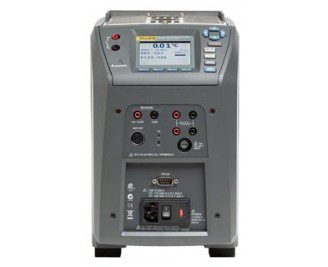
The new 914X Series Field Metrology Wells extend high performance to the industrial process environment by maximizing portability, speed and functionality.
The new 914X Series Field Metrology Wells extend high performance to the industrial process environment by maximizing portability, speed, and functionality with little compromise to metrology performance. Field Metrology Wells are packed
with functionality and are remarkably easy to use. They are lightweight, small, and quick to reach temperature set points, yet they are stable, uniform, and accurate. These industrial temperature loop calibrators are perfect for performing transmitter loop calibrations, comparison calibrations, or simple checks of thermocouple sensors.
With the “process” option, there is no need to carry additional tools into the field. This optional built-in two-channel readout reads resistance, voltage, and 4–20 mA current with 24 volt loop power. It also has on-board automation and documentation. Combined, the three models (9142, 9143, and 9144—each with a “process” option) cover the wide range of –25 °C to 660 °C.
High performance for the industrial environment
Field Metrology Wells are designed for the industrial process environment. They weigh less than 8.2 kg (18 lb) and have a small footprint, which makes them easy to transport. Optimized for speed, Field Metrology Wells cool to –25 °C in 15 minutes and heat to 660 °C in 15 minutes.
Field environment conditions are typically unstable, having wide temperature variations. Each Field Metrology Well has a built-in gradient-temperature compensation (patent pending) that adjusts control characteristics to ensure stable performance in unstable environments. In fact, all specifications are guaranteed over the environmental range of 13 °C to 33 °C.
Lightweight, portable, and fast
Cool to –25 °C in 15 minutes and heat to 660°C in 15 minutes
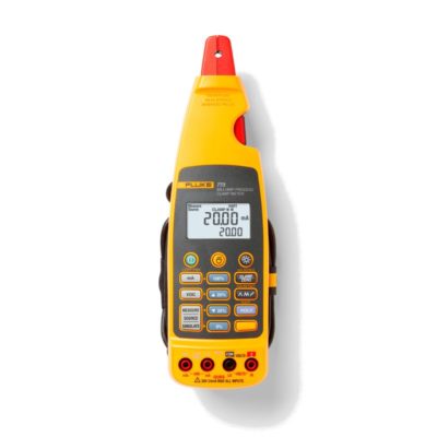
Built-in two-channel readout for PRT, RTD, thermocouple, 4-20 mA current
True reference thermometry with accuracy to ±0.01 °C
On-board automation and documentation
Metrology performance in accuracy, stability, uniformity, and loading
Built-in features to address large workloads and common applications
Whether you need to calibrate 4-20 mA transmitters or a simple thermostatic switch, a Field Metrology Well is the right tool for the job. With three models covering the range of –25 °C to 660 °C, this family of Metrology Wells calibrates a wide range of sensor types. The optional process version (models 914X-X-P) provides a built-in two-channel thermometer readout that measures PRTs, RTDs, thermocouples, and 4-20 mA transmitters which includes the 24 V loop supply to power the transmitter.
Each process version accepts an ITS-90 reference PRT. The built-in readout accuracy ranges from ± 0.01 °C to ± 0.07 °C depending on the measured temperature. Reference PRTs for Field Metrology Wells contain individual calibration constants that reside in a memory chip located inside the sensor housing, so sensors may be used interchangeably. The second channel is user-selectable for 2-, 3-, or 4-wire RTDs, thermocouples, or 4-20 mA transmitters. For comparison calibration, don’t hassle with carrying multiple instruments to the field. Field Metrology Wells do it all as a single instrument.
Traditionally, calibrations of temperature transmitters have been performed on the measurement electronics, while the sensor remained uncalibrated. Studies have shown, however, that typically 75 % of the error in the transmitter system (transmitter electronics and temperature sensor) is in the sensing element. Thus, it becomes important to calibrate the whole loop—both electronics and sensor.
The process option of Field Metrology Wells makes transmitter loop calibrations easy. The transmitter sensor is placed in the well with the reference PRT and the transmitter electronics are connected to the front panel of the instrument. With 24 V loop power, you are able to power and measure the transmitter current while sourcing and measuring temperature in the Field Metrology Well. This allows for the measurement of as-found and as-left data in one self-contained calibration tool.
All Field Metrology Wells allow for two types of automated thermostatic switch test procedures—auto or manual setup. Auto setup requires the entry of only the nominal switch temperature. With this entry, it will run a 3-cycle calibration procedure and provide final results for the dead band temperature via the display. If you need to customize the ramp rate or run additional cycles, the manual setup allows you to program and run the procedure exactly how you would like. Both methods are fast and easy and make testing temperature switches a virtual joy!
Metrology performance for high-accuracy measurements
Unlike traditional dry-wells, Field Metrology Wells maximize speed and portability without compromising the six key metrology performance criteria laid out by the EA: accuracy, stability, axial (vertical) uniformity, radial (well-to-well) uniformity, loading, and hysteresis. All criteria are important in ensuring accurate measurements in all calibration applications. Field Metrology Well displays are calibrated with high-quality traceable and accredited PRTs. Each device (process and non-process versions) comes with an IEC-17025 NVLAP-accredited calibration certificate, which is backed by a robust uncertainty analysis that considers temperature gradients, loading effects, and hysteresis. The 9142 and 9143 have a display accuracy of ± 0.2 °C over their full range, and the 9144 display accuracy ranges from ± 0.35 °C at 420 °C to ± 0.5 °C at ± 660 °C. Each calibration is backed with a 4:1 test uncertainty ratio.
New control technology guarantees excellent performance in extreme environmental conditions. The 9142 is stable to ± 0.01 °C over its full range and the mid-range 9143 is stable from ± 0.02 °C at 33 °C and ± 0.03 °C at 350 °C. Even at 660 °C, the 9144 is stable to ± 0.05 °C. But this is not all! Thermal block characteristics provide radial (well-towell) uniformity performance to ± 0.01 °C. Dual-zone control helps these tools achieve axial uniformity to ± 0.05 °C at 40 mm (1.6 in).
Automation and documentation make each unit a turnkey solution
So you now have a precision calibration instrument that has field-ready characteristics, accredited metrology performance, built-in two-channel thermometry, and automation— what else could you ask for? How about all this and a turnkey solution that will automate and document the results?
The process versions of Field Metrology Wells have onboard non-volatile memory for documentation of up to 20 tests. Each test can be given a unique alphanumeric ID and will record block temperature, reference temperature, UUT values, error, date, and time. Each test can be easily viewed via the front panel or exported using Model 9930 Interface-it software, which is included with each shipment. Interface-itallows you to pull the raw data into a calibration report or an ASCII file.
Operation is as easy as 1-2-3
You’ll find Field Metrology Wells intuitive and easy to use. Each unit is equipped with a large, easy-to-read LCD display, function keys, and menu navigation buttons. Its “SET PT.” button makes it straightforward and simple to set the block temperature. Each product has a stability indicator that visually and audibly tells you the Field Metrology Wells is stable to the selectable criteria. Each unit offers preprogrammed calibration routines stored in memory for easy recall, and all inputs are easily accessible via the front panel of the instrument. Never buy a temperature calibration tool from a company that only dabbles in metrology (or doesn’t even know the word). Metrology Wells from Fluke are designed and manufactured by the same people who equip the calibration laboratories of the world’s leading temperature scientists. These are the people around the world who decide what a Kelvin is! We know a thing or two more about temperature calibration than the vast majority of the world’s dry-well suppliers. Yes, they can connect a piece of metal to a heater and a control sensor. But we invite you to compare all our specs against the few that they publish. (And by the way, we meet our specs!).
Base Unit Specifications
Temperature Range at 23 °C
9142
–25 °C to 150 °C (–13 °F to 302 °F)
9143
33 °C to 350 °C (91 °F to 662 °F)
9144
50 °C to 660 °C (122 °F to 1220 °F)
Display Accuracy
9142
± 0.2 °C Full Range
9143
± 0.2 °C Full Range
9144
± 0.35 °C at 50 °C
± 0.35 °C at 420 °C
± 0.5 °C at 660 °C
Stability
9142
± 0.01 °C Full Range
9143
± 0.02 °C at 33 °C
± 0.02 °C at 200 °C
± 0.03 °C at 350 °C
9144
± 0.03 °C at 50 °C
± 0.04 °C at 420 °C
± 0.05 °C at 660 °C
Axial Uniformity at 40 mm (1.6 in)
9142
± 0.05 °C Full Range
9143
± 0.04 °C at 33 °C
± 0.1 °C at 200 °C
± 0.2 °C at 350 °C
9144
± 0.05 °C at 50 °C
± 0.35 °C at 420 °C
± 0.5 °C at 660 °C
Radial Uniformity
9142
± 0.01 °C Full Range
9143
± 0.01 °C at 33 °C
± 0.015 °C at 200 °C
± 0.02 °C at 350 °C
9144
± 0.02 °C at 50 °C
± 0.05 °C at 420 °C
± 0.10 °C at 660 °C
Loading Effect (with a 6.35 mm reference probe and three 6.35 mm probes)
9142
± 0.006 °C Full Range
9143
± 0.015 °C Full Range
9144
± 0.015 °C at 50 °C
± 0.025 °C at 420 °C
± 0.035 °C at 660 °C
Hysteresis
9142
0.025
9143
0.03
9144
0.1
Operating Conditions
0 °C to 50 °C, 0 % to 90 % RH (non-condensing)
Environmental Conditions (for all specifications except temperature range)
13 °C to 33 °C
Immersion (Well) Depth
150 mm (5.9 in)
Insert OD
9142
30 mm (1.18 in)
9143
25.3 mm (1.00 in)
9144
24.4 mm (0.96 in)
Heating Time
9142
16 min: 23 °C to 140 °C
23 min: 23 °C to 150 °C
25 min: –25 °C to 150 °C
9143
5 min: 33 °C to 350 °C
9144
15 min: 50 °C to 660 °C
Cooling Time
9142
15 min: 23 °C to –25 °C
25 min: 150 °C to –23 °C
9143
32 min: 350 °C to 33 °C
14 min: 350 °C to 100 °C
9144
35 min: 660 °C to 50 °C
25 min: 660 °C to 100 °C
Resolution
0.01 °
Display
LCD, °C or °F user-selectable
Size (H x W x D)
290 mm x 185 mm x 295 mm (11.4 x 7.3 x 11.6 in)
Weight
9142
8.16 kg (18 lb)
9143
7.3 kg (16 lb)
9144
7.7 kg (17 lb)
Power Requirements
9142
100 V to 115 V (± 10 %) 50/60 Hz, 635 W 230 V (± 10 %) 50/60 Hz, 575 W
9143 9144
100 V to 115 V (± 10 %), 50/60 Hz, 1400 W 230 V (± 10 %), 50/60 Hz, 1800 W
Computer Interface
RS-232 and 9930 Interface-it control software included
± 0.010 °C at -25 °C
± 0.015 °C at 0 °C
± 0.020 °C at 50 °C
± 0.025 °C at 150 °C
± 0.030 °C at 200 °C
± 0.040 °C at 350 °C
± 0.050 °C at 420 °C
± 0.070 °C at 660 °C
Reference Resistance Range
0 ohms to 400 ohms
Reference Resistance Accuracy‡
0 ohms to 42 ohms: ±0.0025 ohms 42 ohms to
400 ohms: ±60 ppm of reading
Reference Characterizations
ITS-90, CVD, IEC-751, Resistance
Reference Measurement Capability
4-wire
Reference Probe Connection
6-pin Din with Infocon Technology
Built-in RTD Thermometer Readout Accuracy
NI-120: ± 0.015 °C at 0 °C
PT-100 (385): ± 0.02 °C at 0 °C
PT-100 (3926): ± 0.02 °C at 0 °C
PT-100 (JIS): ± 0.02 °C at 0 °C
RTD Resistance Range
0 ohms to 400 ohms
RTD Resistance Accuracy‡
0 ohms to 25 ohms: ±0.002 ohms
25 ohms to 400 ohms: ±80 ppm of reading
RTD Characterizations
PT-100 (385),(JIS),(3926), NI-120, Resistance
RTD Measurement Capability
4-wire RTD (2-,3-wire RTD w Jumpers only)
RTD Connection
4 terminal input
Built-in TC Thermometer Readout Accuracy
Type J: ± 0.7 °C at 660 °C
Type K: ± 0.8 °C at 660 °C
Type T: ± 0.8 °C at 400 °C
Type E: ± 0.7 °C at 660 °C
Type R: ± 1.4 °C at 660 °C
Type S: ± 1.5 °C at 660 °C
Type M: ± 1.4 °C at 660 °C
Type L: ± 0.7 °C at 660 °C
Type U: ± 0.75 °C at 600 °C
Type N: ± 0.9 °C at 660 °C
Type C: ± 1.1 °C at 660 °C
TC Millivolt Range
–10 mV to 75 mV
Voltage Accuracy
0.025% of reading + 0.01 mV
Internal Cold Junction Compensation Accuracy
± 0.35 °C (ambient of 13 °C to 33 °C)
TC Connection
Small connectors
Built-in mA Readout Accuracy
0.02 % of reading + 2 mV
mA Range
Cal 4-22 mA, Spec 4-24 mA
mA Connection
2 terminal input
Loop Power Function
24 V DC loop power
Built-in Electronics Temperature Coefficient (0 °C to 13 °C, 33 °C to 50 °C)
± 0.005 % of range per °C
† The temperature range may be limited by the reference probe connected to the readout. The Built-In Reference Thermometer Readout Accuracy does not include the sensor probe accuracy. It does not include the probe uncertainty or probe characterization errors.
‡ Measurement accuracy specifications apply within the operating range and assume 4-wires for PRTs. With 3-wire RTDs add 0.05 ohms to the measurement accuracy plus the maximum possible difference between the resistances of the lead wires.
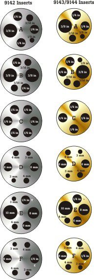
X in the above model numbers to be replaced with A, B, C, D, E, or F as appropriate for the desired insert. See the inserts illustration and listing below.
Model Name
Description
9142-X
Field Metrology Well, –25 °C to 150 °C, w/9142-INSX
X in the model number to be replaced with A, B, C, D, E, or F as appropriate for the desired insert. (See illustration on Description tab.)
Insert Custom 9142
Custom insert pricing is based on a maximum of eight holes. Please contact your local sales representative if you have special requirements.
9142-INSZ
Insert “Z” 9142, Blank
9142-X-P
Field Metrology Well, –25 °C to 150 °C, w/9142-INSX, w/Process Electronics
X in the model number to be replaced with A, B, C, D, E, or F as appropriate for the desired insert. (See illustration on Description tab.)
Insert Custom 9142
Custom insert pricing is based on a maximum of eight holes. Please contact your local sales representative if you have special requirements.
9142-INSZ
Insert “Z” 9142, Blank
9143-X
Field Metrology Well, 33 °C to 350 °C, w/9143-INSX
X in the model number to be replaced with A, B, C, D, E, or F as appropriate for the desired insert. (See illustration on Description tab.)
Insert Custom 9143
Custom insert pricing is based on a maximum of eight holes. Please contact your local sales representative if you have special requirements.
9143-INSZ
Insert “Z” 9143, Blank
9143-X-P
Field Metrology Well, 33 °C to 350 °C, w/9143-INSX, w/Process Electronics
X in the model number to be replaced with A, B, C, D, E, or F as appropriate for the desired insert. (See illustration on Description tab.)
Insert Custom 9143
Custom insert pricing is based on a maximum of eight holes. Please contact your local sales representative if you have special requirements.
9143-INSZ
Insert “Z” 9143, Blank
9144-X
Field Metrology Well, 50 °C to 660 °C, w/9144-INSX
X in the model number to be replaced with A, B, C, D, E, or F as appropriate for the desired insert. (See illustration on Description tab.)
Insert Custom 9144
Custom insert pricing is based on a maximum of eight holes. Please contact your local sales representative if you have special requirements.
9144-INSZ
Insert “Z” 9144, Blank
9144-X-P
Field Metrology Well, 50 °C to 660 °C, w/9144-INSX, w/Process Electronics
X in the model number to be replaced with A, B, C, D, E, or F as appropriate for the desired insert. (See illustration on Description tab.)
Insert Custom 9144
Custom insert pricing is based on a maximum of eight holes. Please contact your local sales representative if you have special requirements.
At Minerva we believe that measuring gives us the possibility to improve. We use cookies to ensure that our website works properly, to analyze and improve it. If you prefer not to place cookies, adjust your settings or click refuse. Also read our privacy statement.

 New control technology guarantees excellent performance in extreme environmental conditions. The 9142 is stable to ± 0.01 °C over its full range and the mid-range 9143 is stable from ± 0.02 °C at 33 °C and ± 0.03 °C at 350 °C. Even at 660 °C, the 9144 is stable to ± 0.05 °C. But this is not all! Thermal block characteristics provide radial (well-towell) uniformity performance to ± 0.01 °C. Dual-zone control helps these tools achieve axial uniformity to ± 0.05 °C at 40 mm (1.6 in).