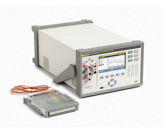
Fluke 1586A Super-DAQ Precision Temperature Scanner
The 1586A Super‑DAQ is the most accurate and flexible temperature data acquisition system on the market.
Highlights of Fluke 1586A Super-DAQ Precision Temperature Scanner
The 1586A Super‑DAQ is the most accurate and flexible temperature data acquisition system on the market. It scans and records temperature, dc voltage, dc current, and resistance for up to 40 input channels and scan speeds as fast as 10 channels per second. The Super-DAQ can be configured for use as a multi-channel data logger in the factory or as a precision reference thermometer for benchtop sensor calibration in the lab.
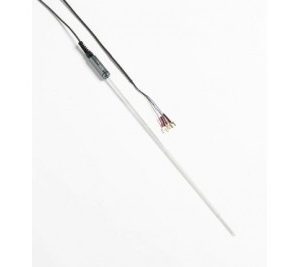
- Measure thermocouples, PRTs, thermistors, dc voltage, dc current, and resistance
- Best-in-class temperature measurement accuracy
- PRTs ± 0.005 °C (using external DAQ‑STAQ Multiplexer)
- Thermocouples: ± 0.5 °C (using High-Capacity Module and internal CJC)
- Thermistors: ± 0.002 °C
- Input channels: Up to 40 isolated universal inputs
- Flexible configuration: Internal High-Capacity Module and/or DAQ-STAQ Multiplexer
- Selectable scan speed: Up to 10 channels per second
- Four modes of operation: Scan, Monitor, Measure, Digital Multimeter (DMM)
- Real-time color trending: Chart up to four channels simultaneously
- 6 1/2 digit display resolution for dc voltage, dc current, and resistance
- Current reversal minimizes thermoelectric effects, improving PRT/RTD measurment accuracy
- Automated sensor calibration: Control Fluke Calibration temperature sources such as dry-wells or micro-baths for automated calibration routines
- Data storage: Records up to 20 MB of data and setup files to internal non-volatile memory or to an external USB drive. Transfer data to a PC using the USB drive or LAN connection and view data in Microsoft® Excel
- Data security: Administrator and user profiles for protecting settings and ensuring test traceability
- Mx + B scaling and channel offset zero function
- Alarms: Two independent, user-defined alarms for each channel indicate when an upper or lower range has been exceeded
Fluke 1586A Super-DAQ Precision Temperature Scanner
The 1586A Super-DAQ collects time-stamped precision temperature and electrical measurements for data analysis by technicians, engineers, and quality control personnel to verify process control, analyze interactive systems, ensure conformance to quality standards, or to correlate related events for R&D or troubleshooting. Measurement data and statistics can be viewed in tabular format for all active channels. With the graphing feature, up to four channels can be plotted at the same time, making it easy to quickly assess test setup and results before analyzing the data on a PC.
When configured with the DAQ-STAQ Multiplexer, the Super-DAQ has the accuracy of the best benchtop reference thermometer readouts for calibration of PRTs, RTDs, thermistors, or thermocouples. Lab efficiency can be increased when the Super-DAQ is connected to a Fluke Calibration drywell or bath and Automated Sensor Test routines are run.
The 1586 is ideal for a number of applications such as thermal mapping, temperature validation, process sensor calibration, and more. These applications are found in a various industries including pharmaceutical, biotechnology, food processing, aerospace, and automotive.
There are six key features that set the Super-DAQ apart from other products in its class:
- Best temperature measurement accuracy
- Flexible configuration for the factory or benchtop
- Multiple modes of operation
- Real-time graphing in color
- Data portability and security
- Automated sensor calibration
1. Best temperature measurement accuracy
The 1586A Super-DAQ reads PRTs, thermocouples, and thermistors with best-in-class accuracy:
- PRTs ± 0.005 °C (using external DAQ-STAQ Multiplexer)
- Thermocouples: ± 0.5 °C (using High-Capacity Module and internal CJC)
- Thermistors: ± 0.002 °C
2. Flexible configuration for the factory or benchtop
For factory applications, the Super-DAQ is configured with the internal High-Capacity Module. Connecting thermocouples or RTDs to input terminals can be time consuming—especially if you're using many sensors of the same type for one job, and then switching to a different sensor type for another job. The internal High-Capacity Module allows you to pre-configure multiple input modules and simply exchange one module for another, depending on your test requirements. Recall a stored test setup to make the changeover even faster. And if you prefer, you can always measure a variety of different input types at the same time in a single High-Capacity Module, including thermocouples, RTDs, voltage, resistance, or current.
For a calibration lab where accuracy is of primary importance, the Super-DAQ is best configured with a DAQ-STAQ Multiplexer. The external DAQ-STAQ features mini-jack thermocouple terminals—each with its own reference junction sensor—and patented mini-DWF, gold-plated input terminals, which accept bare wire, spade lug, or mini-banana-plug terminations. Easily connect and disconnect PRTs, thermistors, and thermocouples for benchtop temperature calibration. It can be stacked on the 1586 to reduce footprint in busy labs. Flexibility to configure the Super-DAQ for factory or calibration lab use reduces your equipment needs and cost.
3. Multiple modes of operation
The Super-DAQ can operate in four modes that let you scan, monitor, measure, or function as a digital multimeter from a single instrument. Sequentially scan through channels based on a user defined test. Monitor any single channel during a scan, without interrupting the scan. Measure and record data on a single channel without the need of a pre-configured test file. Or in DMM mode, use the front panel channel like a familiar benchtop digital multimeter to quickly measure dc voltage, dc current, or 2-wire and 4-wire resistance without the need to configure the channel.
4. Real-time graphing in color
Most data acquisition systems only let you view data on one channel. But now the Super-DAQ, lets you view real time data for all channels in table format, or you can chart up to four channels in color at the same time. You can zoom in or out to see data of interest and monitor trends. A history mode lets you scroll through collected data within a scan file—all without a PC and expensive charting programs. Switch between chart view and table view of various measurement data and statistics
5. Data portability and security
The Super-DAQ includes 20 MB internal memory that can store over 75,000 time-stamped readings. Data and set-up files can be easily moved to a PC for analysis using a USB flash drive or over a network using the LAN interface connection. The Super-DAQ also includes two levels of data security to prevent unauthorized users from tampering with or forging test data or setup files. This security feature is especially important to industries that are regulated by government agencies where data traceability is required.
6. Automated sensor calibration
With the Automated Test feature, you can automate sensor calibration without a PC and software. When connected to a Fluke Calibration drywell or fluid bath via the RS-232 interface, the Super-DAQ takes control of the temperature source and runs your calibration automatically. You simply program the number of setpoint temperatures and their values, select a scan sequence (linear, alternate, up/down), assign a reference channel, and set the required stability band. The Super-DAQ monitors the temperature source's stability via the reference channel, collects the data once stabilized, and then advances to the next setpoint temperature. After you configure and start the test, you can walk away to work on other things. The Super-DAQ just made your day a whole lot easier.
General Specifications |
|
| Mains Voltage | 100 V Setting: 90 V to 110 V 120 V Setting: 108 V to 132 V 220 V Setting: 198 V to 242 V 240 V Setting: 216 V to 264 V |
| Frequency | 47 Hz to 440 Hz |
| Power Consumption | 36 VA peak (24 W average) |
| Environment Temperature | Operating: 0 °C to 50 °C Full accuracy: 18 °C to 28 °C Storage: −20 °C to 70 °C Warm-up: 1 hour to full accuracy specifications |
| Relative Humidity (non-condensing) | Operating: 0 °C to 30 °C < 80 %; 30 °C to 50 °C < 50 % Storage: −20 °C to 70 °C < 95 % |
| Altitude | Operating: 2,000 m Storage: 12,000 m |
| Vibration and Shock | Complies with MIL-PRF-28800F Class 3 |
| Channel Capacity | Total analog channels: 45 Voltage/resistance channels: 41 Current channels: 5 Digital I/O: 8 bits Totalizer: 1 Alarm outputs: 6 Trigger input: 1 |
| Input Protection | 50 V all functions, terminals and ranges |
| Math Channels | Number of channels: 20 Operations: sum, difference, multiply, divide, polynomial, power, square root, reciprocal, exponential, logarithm, absolute value, average, maximum, minimum |
| Triggers | interval, external (trigger input), alarm, remote (bus), manual, automated test |
| Memory | Scan data RAM: 75,000 readings with timestamp Data/Setup flash memory: 20 MB |
| USB Host Port | Connector type: Type A Function: Memory File system: FAT32 Memory capacity: 32 GB |
| USB Device Port | Connector type: Type B Class: Instrument Function: Control and data transfer Command protocol: SCPI |
| LAN | Function: Control and data transfer Network protocols: Ethernet 10/100, TCP/IP Command protocol: SCPI |
| RS-232 | Connector: D-sub 9 pin (DE-9) Baud rates: 1200, 2400, 4800, 9600, 19200, 38400 Function: Temperature source control output |
| Dimensions | Height: 150 mm Width: 245 mm Depth: 385 mm Weight: 6 kg (typical configuration) Shipping Weight: 9.5 kg (typical configuration) |
| Conformity | CE, CSA, IEC 61010 3rd ed. |
Measurement Specifications |
|
| Accuracy specifications generally apply with medium and slow sample rates (unless otherwise noted), after a warm-up time of 1 hour, and within an environment temperature range of 18 °C to 28 °C, and may depend on the channel. The confidence level for accuracy specifications is 95 % within 1 year of calibration. | |
| Scan rate | Fast: 10 channels per second max (0.1 seconds per channel) Medium: 1 channel per second (1 second per channel) Slow: 4 seconds per channel |
| Display Resolution | 6 1/2 digits (see Measurement Characteristics tables below to find the display resolution of temperature readings) |
PRT/RTD |
|
| Temperature Range | −200 °C to 1200 °C (depending on the sensor) |
| Resistance Range | 0 Ω to 4 kΩ |
| Offset Compensation | 0 Ω to 400 Ω, 4-wire: automatic current reversal 400 Ω to 4000 Ω or 3-wire: none |
| Source Current Reversal Interval (0 Ω to 400 Ω range) | Fast sample rate: 2 ms Medium sample rate: 250 ms Slow sample rate: 250 ms |
| Maximum Lead Resistance (4-wire Ω) | 2.5 % of range per lead for 400 Ω and 4 kΩ ranges |
PRT/RTD Resistance Accuracy |
||||
| Accuracy is given as % of measurement or ohms, whichever is greater. Basic accuracy is for 4-wire PRT/RTD. When using 3-wire PRT/RTD add 0.013 Ω to the accuracy specification for internal resistance mismatch and voltage offset if using Channel 1, or add 0.05 Ω if using channels x01 through x20. If the environment temperature is outside the specified range, multiply the temperature coefficient numbers by the temperature deviation and add to the accuracy specification. | ||||
| Range | Sample Rate | DAQ-STAQ Module and Channel 1 | High-Capacity Module | T.C./ °C Outside 18 °C to 28 °C |
| 0 Ω to 400 Ω | Slow | 0.002 % or 0.0008 Ω | 0.003 % or 0.003 Ω | 0.0001 % or 0.0008 Ω |
| Medium | 0.002 % or 0.002 Ω | 0.003 % or 0.003 Ω | 0.0001 % or 0.0008 Ω | |
| Fast | 0.002 % or 0.005 Ω | 0.003 % or 0.006 Ω | 0.0001 % or 0.0008 Ω | |
| 400 Ω to 4 kΩ | Slow | 0.004 % or 0.06 Ω | 0.006 % or 0.06 Ω | 0.0001 % or 0.008 Ω |
| Medium | 0.004 % or 0.1 Ω | 0.006 % or 0.1 Ω | 0.0001 % or 0.008 Ω | |
| Fast | 0.004 % or 0.18 Ω | 0.006 % or 0.18 Ω | 0.0001 % or 0.008 Ω |
PRT/RTD Temperature Accuracy |
||||
| Accuracy is for 4-wire 100 Ω nominal PRT/RTD. When using 3-wire PRT/RTD add 0.039 °C to the accuracy specification for internal resistance mismatch and voltage offset if using Channel 1, or add 0.15 °C if using channels x01 through x20. If the environment temperature is outside the specified range, multiply the temperature coefficient number by the temperature deviation and add to the accuracy specification. Linear interpolation may be used between points in the table. Specifications do not include sensor accuracy. The practical range of temperature measurement depends on the sensor and characterization. | ||||
| Sample Rate | Temperature | DAQ-STAQ Module and Channel 1 | High-Capacity Module | T.C./ °C Outside 18 °C to 28 °C |
| Slow | −200 °C | 0.002 °C | 0.008 °C | 0.002 °C |
| 0 °C | 0.005 °C | 0.008 °C | 0.003 °C | |
| 300 °C | 0.012 °C | 0.018 °C | 0.006 °C | |
| 600 °C | 0.02 °C | 0.03 °C | 0.01 °C | |
| Medium | −200 °C | 0.005 °C | 0.008 °C | 0.002 °C |
| 0 °C | 0.005 °C | 0.008 °C | 0.003 °C | |
| 300 °C | 0.012 °C | 0.018 °C | 0.006 °C | |
| 600 °C | 0.02 °C | 0.03 °C | 0.01 °C | |
| Fast | −200 °C | 0.013 °C | 0.015 °C | 0.002 °C |
| 0 °C | 0.013 °C | 0.015 °C | 0.003 °C | |
| 300 °C | 0.014 °C | 0.018 °C | 0.006 °C | |
| 600 °C | 0.02 °C | 0.03 °C | 0.01 °C |
PRT/RTD Measurement Characteristics |
|||
| Temperature Display Resolution | |||
| Range | Slow / Medium Sample Rate | Fast Sample Rate | Source Current |
| 0 Ω to 400 Ω | 0.001 °C | 0.01 °C | ±1 mA |
| 400 Ω to 4 kΩ | 0.001 °C | 0.01 °C | 0.1 mA |
Thermistor |
||||
| Temperature Range | −200 °C to 400 °C (depending on the sensor) | |||
| Resistance Range | 0 Ω to 1 MΩ | |||
Thermistor Resistance Accuracy |
||||
| Accuracy is given as ± (% of measurement + Ω). The basic accuracy specification is for 4-wire thermistor, slow sample rate. When using medium or fast sample rate, add the number given in the table to the accuracy specification. If the environment temperature is outside the specified range, multiply the temperature coefficient numbers by the temperature deviation and add to the accuracy specification. For 2-wire thermistor add 0.02 Ω internal resistance if using Channel 1 or 1.5 Ω if using channels x01 through x20, and add external lead wire resistance. |
||||
| Range | Slow Sample Rate | Medium Sample Rate Rate | Fast Sample Rate | T.C./ °C Outside18 °C to 28 °C |
| 0 Ω to 2.2 Ω | 0.004 % + 0.2 Ω | add 0.3 Ω | add 1 Ω | 0.0005 % + 0.05 Ω |
| 2.1 Ω to 98 Ω | 0.004 % + 0.5 Ω | add 0.5 Ω | add 1.3 Ω | 0.0005 % + 0.1 Ω |
| 95 Ω to 1 MΩ | 0.015 % + 5 Ω | add 5 Ω | add 13 Ω | 0.001 % + 2 Ω |
Thermistor Temperature Accuracy |
||||
| Accuracy specifications are for 4-wire thermistor. When using 2-wire thermistor, add the number given in the table to the specification for internal resistance. If the environment temperature is outside the specified range, increase the accuracy specification by 25 % for every 1 °C outside the specified environment temperature range. Specifications do not include sensor accuracy. The practical range of temperature measurement depends on the sensor. | ||||
| Accuracy 2.2 Ω Thermistor | ||||
| Temperature | SlowSample Rate | MediumSample Rate | FastSample Rate | 2-wire |
| −40 °C | 0.001 °C | 0.001 °C | 0.01 °C | add 0.001 °C |
| 0 °C | 0.003 °C | 0.004 °C | 0.01 °C | add 0.004 °C |
| 25 °C | 0.006 °C | 0.011 °C | 0.02 °C | add 0.016 °C |
| 50 °C | 0.008 °C | 0.018 °C | 0.04 °C | add 0.05 °C |
| 100 °C | 0.047 °C | 0.114 °C | 0.28 °C | add 0.34 °C |
| 150 °C | 0.23 °C | 0.56 °C | 1.34 °C | add 1.7 °C |
| Accuracy 5 Ω Thermistor | ||||
| Temperature | Slow Sample Rate | Medium Sample Rate | Fast Sample Rate | 2-wire |
| −40 °C | 0.003 °C | 0.004 °C | 0.01 °C | add 0.001 °C |
| 0 °C | 0.002 °C | 0.002 °C | 0.01 °C | add 0.002 °C |
| 25 °C | 0.004 °C | 0.006 °C | 0.01 °C | add 0.007 °C |
| 50 °C | 0.005 °C | 0.009 °C | 0.02 °C | add 0.022 °C |
| 100 °C | 0.022 °C | 0.052 °C | 0.13 °C | add 0.16 °C |
| 150 °C | 0.096 °C | 0.24 °C | 0.57 °C | add 0.7 °C |
| Accuracy 10 Ω Thermistor | ||||
| Temperature | Slow Sample Rate | Medium Sample Rate | Fast Sample Rate | 2-wire |
| −40 °C | 0.003 °C | 0.004 °C | 0.01 °C | add 0.001 °C |
| 0 °C | 0.002 °C | 0.002 °C | 0.01 °C | add 0.002 °C |
| 25 °C | 0.003 °C | 0.004 °C | 0.01 °C | add 0.004 °C |
| 50 °C | 0.005 °C | 0.009 °C | 0.02 °C | add 0.011 °C |
| 100 °C | 0.011 °C | 0.024 °C | 0.06 °C | add 0.067 °C |
| 150 °C | 0.04 °C | 0.098 °C | 0.24 °C | add 0.29 °C |
Thermistor Measurement Characteristics |
|||
| Temperature Display Resolution | |||
| Range | Slow / Medium Sample Rate |
Fast Sample Rate |
Source Current |
| 0 Ω to 2.2 Ω | 0.0001 °C | 0.001 °C | 10 μA |
| 2.1 Ω to 98 Ω | 0.0001 °C | 0.001 °C | 10 μA |
| 95 Ω to 1 MΩ | 0.0001 °C | 0.001 °C | 1 μA |
Thermocouple |
||||
| Temperature Range | −270 °C to 2315 °C (depending on the sensor) | |||
| Voltage Range | −15 mV to 100 mV | |||
Thermocouple Voltage Accuracy |
||||
| Accuracy is given as ± (|% of measurement| + μV). Basic accuracy specification is for medium or slow sample rate. When using a fast sample rate add the number given in the table to the accuracy specification. If the environment temperature is outside the specified range, multiply the temperature coefficient numbers by the temperature deviation and add to the accuracy specification. | ||||
| Range | Accuracy Channel 1 | Ch. x01 – x20 | Fast Sample Rate | T.C./ °C Outside 18 °C to 28 °C |
| −15 mV to 100 mV | 0.004 % + 4 μV | add 2 μV | add 1 μV | 0.0005 % + 0.0005 mV |
Thermocouple Reference Junction Accuracy |
||
| Module | CJC Accuracy | T.C./ °C Outside 18 °C to 28 °C |
| DAQ-STAQ Module | 0.25 °C | 0.02 °C |
| High-Capacity Module | 0.6 °C | 0.05 °C |
Thermocouple Temperature Accuracy |
|||||
| Accuracy specifications apply using medium or slow sample rate. When using fast sample rate, increase the accuracy specification by 25 %. If the environment temperature is outside the specified range, increase the accuracy specification by 12 % for every 1 °C outside the specified environment temperature range. Accuracy with fixed/external CJC does not include the accuracy of the reference junction temperature. Linear interpolation may be used between points in the table. Specifications do not include sensor accuracy. The practical range of temperature measurement depends on the sensor. | |||||
| Type (Range) |
Temperature | Accuracy | |||
| Fixed / External CJC | Internal CJC | ||||
| Channel 1 | Ch. x01 – x20 | DAQ-STAQ Module | High-Capacity Module |
||
| K −270 °C to 1372 °C |
−200 °C 0 °C 1000 °C |
0.28 °C 0.10 °C 0.14 °C |
0.41 °C 0.15 °C 0.20 °C |
0.76 °C 0.29 °C 0.32 °C |
1.60 °C 0.62 °C 0.64 °C |
| T −270 °C to 400 °C |
−200 °C 0 °C 200 °C 400 °C |
0.27 °C 0.10 °C 0.08 °C 0.08 °C |
0.40 °C 0.15 °C 0.12 °C 0.11 °C |
0.76 °C 0.30 °C 0.23 °C 0.20 °C |
1.60 °C 0.65 °C 0.47 °C 0.41 °C |
| R −50 °C to 1768 °C |
0 °C 300 °C 1200 °C 1600 °C |
0.76 °C 0.42 °C 0.33 °C 0.34 °C |
1.13 °C 0.63 °C 0.47 °C 0.49 °C |
1.16 °C 0.64 °C 0.48 °C 0.50 °C |
1.28 °C 0.71 °C 0.52 °C 0.54 °C |
| S −50 °C to 1768 °C |
0 °C 300 °C 1200 °C 1600 °C |
0.74 °C 0.45 °C 0.37 °C 0.39 °C |
1.11 °C 0.67 °C 0.54 °C 0.56 °C |
1.14 °C 0.68 °C 0.55 °C 0.57 °C |
1.26 °C 0.76 °C 0.60 °C 0.63 °C |
| J −210 °C to 1200 °C |
−200 °C 0 °C 1000 °C |
0.20 °C 0.08 °C 0.11 °C |
0.29 °C 0.12 °C 0.14 °C |
0.65 °C 0.28 °C 0.25 °C |
1.41 °C 0.61 °C 0.53 °C |
| N −270 °C to 1300 °C |
−200 °C 0 °C 500 °C 1000 °C |
0.42 °C 0.15 °C 0.12 °C 0.14 °C |
0.62 °C 0.23 °C 0.17 °C 0.19 °C |
0.90 °C 0.34 °C 0.24 °C 0.26 °C |
1.69 °C 0.64 °C 0.44 °C 0.45 °C |
| E −270 °C to 1000 °C |
−200 °C 0 °C 300 °C 700 °C |
0.17 °C 0.07 °C 0.06 °C 0.08 °C |
0.25 °C 0.10 °C 0.09 °C 0.10 °C |
0.64 °C 0.27 °C 0.21 °C 0.21 °C |
1.42 °C 0.61 °C 0.46 °C 0.45 °C |
| B 100 °C to 1820 °C |
300 °C 600 °C 1200 °C 1600 °C |
1.32 °C 0.68 °C 0.41 °C 0.38 °C |
1.97 °C 1.02 °C 0.60 °C 0.55 °C |
1.97 °C 1.02 °C 0.60 °C 0.55 °C |
1.97 °C 1.02 °C 0.60 °C 0.55 °C |
| C 0 °C to 2315 °C |
600 °C 1200 °C 2000 °C |
0.23 °C 0.28 °C 0.44 °C |
0.33 °C 0.40 °C 0.60 °C |
0.37 °C 0.45 °C 0.66 °C |
0.54 °C 0.63 °C 0.91 °C |
| D 0 °C to 2315 °C |
600 °C 1200 °C 2000 °C |
0.22 °C 0.26 °C 0.39 °C |
0.32 °C 0.36 °C 0.53 °C |
0.34 °C 0.39 °C 0.56 °C |
0.44 °C 0.49 °C 0.69 °C |
| G 0 °C to 2315 °C |
600 °C 1200 °C 2000 °C |
0.24 °C 0.22 °C 0.33 °C |
0.36 °C 0.32 °C 0.46 °C |
0.36 °C 0.32 °C 0.46 °C |
0.36 °C 0.33 °C 0.46 °C |
| L −200 °C to 900 °C |
−200 °C 0 °C 800 °C |
0.13 °C 0.08 °C 0.09 °C |
0.19 °C 0.12 °C 0.12 °C |
0.45 °C 0.28 °C 0.23 °C |
0.99 °C 0.62 °C 0.48 °C |
| M −50 °C to 1410 °C |
0 °C 500 °C 1000 °C |
0.11 °C 0.10 °C 0.10 °C |
0.16 °C 0.15 °C 0.14 °C |
0.30 °C 0.25 °C 0.21 °C |
0.64 °C 0.51 °C 0.41 °C |
| U −200 °C to 600 °C |
−200 °C 0 °C 400 °C |
0.25 °C 0.10 °C 0.08 °C |
0.37 °C 0.15 °C 0.11 °C |
0.71 °C 0.30 °C 0.20 °C |
1.48 °C 0.63 °C 0.40 °C |
| W 0 °C to 2315 °C |
600 °C 1200 °C 2000 °C |
0.24 °C 0.22 °C 0.33 °C |
0.36 °C 0.32 °C 0.46 °C |
0.36 °C 0.32 °C 0.46 °C |
0.36 °C 0.33 °C 0.46 °C |
Thermocouple Measurement Characteristics |
||
| Range | Temperature Display Resolution | |
| Slow / Medium Sample Rate |
Fast Sample Rate |
|
| −270 °C to 2315 °C | 0.01 °C | 0.1 °C |
DC Voltage |
||||
| Maximum Input | 50 V on any range | |||
| Common Mode Rejection | 140 dB at 50 Hz or 60 Hz (1 kΩ unbalance in LOW lead) ±50 V peak maximum | |||
| Normal Mode Rejection | 55 dB for power line frequency ±0.1 %, ±120 % of range peak maximum | |||
| A/D Linearity | 2 ppm of measurement + 1 ppm of range | |||
| Input Bias Current | 30 pA at 25 °C | |||
DC Voltage Accuracy |
||||
| Accuracy is given as ± (% measurement + % of range). Basic accuracy specification is for Channel 1, medium or slow sample rate. For channels x01 through x20 or when using Fast sample rate, add the numbers given in the table to the accuracy specification. If the environment temperature is outside the specified range, multiply the temperature coefficient numbers by the temperature deviation and add to the accuracy specification. | ||||
| Range | Accuracy Channel 1 | Ch. x01 – x20 | Fast Sample Rate | T.C./ °C Outside 18 °C to 28 °C |
| ±100 mV | 0.0037 % + 0.0035 % | add 2 μ | add 0.0008 % of range | 0.0005 % + 0.0005 % |
| ±1 V | 0.0025 % + 0.0007 % | add 2 μ | add 0.0008 % of range | 0.0005 % + 0.0001 % |
| ±10 V | 0.0024 % + 0.0005 % | − | add 0.0008 % of range | 0.0005 % + 0.0001 % |
| ±50 V | 0.0038 % + 0.0012 % | − | add 0.0008 % of range | 0.0005 % + 0.0001 % |
DC Voltage Input Characteristics |
||||
| Resolution | Input Impedance | |||
| Range | Slow / Medium | Fast | ||
| ±100 mV | 0.1 μ | 1 μ | 10 GΩ [1] | |
| ±1 V | 1 μ | 10 μ | 10 GΩ [1] | |
| ±10 V | 10 μ | 100 μ | 10 GΩ [1] | |
| ±50 V | 100 μ | 1 mV | 10 MΩ ±1 % | |
| [1] - Input beyond ±12 V is clamped. The clamp current is up to 3 mA. |
DC Current |
|||
| Input Protection | 0.15 A resettable PTC | ||
DC Current Accuracy |
|||
| Accuracy is given as ± (% measurement + % of range). Basic accuracy specification is for medium or slow sample rate. When using a fast sample rate, add the number given in the table to the accuracy specification. If the environment temperature is outside the specified range, multiply the temperature coefficient numbers by the temperature deviation and add to the accuracy specification. | |||
| Range | Accuracy | Fast Sample Rate | T.C./ °C Outside 18 °C to 28 °C |
| ±100 μA | 0.015 % + 0.0035 % | add 0.0008 % of range | 0.002 % + 0.001 % |
| ±1 mA | 0.015 % + 0.0011 % | add 0.0008 % of range | 0.002 % + 0.001 % |
| ±10 mA | 0.015 % + 0.0035 % | add 0.0008 % of range | 0.002 % + 0.001 % |
| ±100 mA | 0.015 % + 0.0035 % | add 0.0008 % of range | 0.002 % + 0.001 % |
DC Current Input Characteristics |
|||
| Resolution | |||
| Range | Slow / Medium | Fast | Burden Voltage |
| ±100 μA | 0.1 nA | 1 nA | < 1 mV |
| ±1 mA | 1 nA | 10 nA | < 1 mV |
| ±10 mA | 10 nA | 100 nA | < 1 mV |
| ±100 mA | 100 nA | 1 μA | < 1 mV |
Resistance |
|||
| Max. Lead Resistance (4-wire ohms) | 10 Ω per lead for 100 Ω and 1 kΩ ranges. 1 kΩ per lead on all other ranges. | ||
Resistance Accuracy |
|||
| Accuracy is given as ± (% measurement + % of range). Basic accuracy specification is for 4-wire resistance, medium or slow sample rate. For 2-wire resistance add 0.02 Ω internal resistance if using Channel 1, or 1.5 Ω if using channels x01 through x20, and add external lead wire resistance. When using Fast sample rate, add the numbers given in the table to the accuracy specification. If the environment temperature is outside the specified range, multiply the Temperature Coefficient numbers by the temperature deviation and add to the accuracy specification | |||
| Range | Accuracy | Fast Sample Rate | 1T.C./ °C Outside 8 °C to 28 °C |
| 100 Ω | 0.004 % + 0.0035 % | add 0.001 % of range | 0.0001 % + 0.0005 % |
| 1 kΩ | 0.003 % + 0.001 % | add 0.001 % of range | 0.0001 % + 0.0001 % |
| 10 kΩ | 0.004 % + 0.001 % | add 0.001 % of range | 0.0001 % + 0.0001 % |
| 100 kΩ | 0.004 % + 0.001 % | add 0.001 % of range | 0.0001 % + 0.0001 % |
| 1 MΩ | 0.006 % + 0.001 % | add 0.002 % of reading plus 0.0008 % of range | 0.0005 % + 0.0002 % |
| 10 MΩ | 0.015 % + 0.001 % | add 0.002 % of reading plus 0.0008 % of range | 0.001 % + 0.0004 % |
| 100 MΩ | 0.8 % + 0.01 % | add 0.01 % of range | 0.05 % + 0.002 % |
Resistance Input Characteristics |
|||
| Range | Resolution Slow / Medium |
Fast | Source Current (open-circuit voltage) |
| 100 Ω | 0.1 mΩ | 1 mΩ | 1 mA (4 V) |
| 1 kΩ | 1 mΩ | 10 mΩ | 1 mA (4 V) |
| 10 kΩ | 10 mΩ | 100 mΩ | 100 μA (6 V) |
| 100 kΩ | 100 mΩ | 1 Ω | 100 μA (12 V) |
| 1 MΩ | 1 Ω | 10 Ω | 10 μA (12 V) |
| 10 MΩ | 10 Ω | 100 Ω | 1 μA (12 V) |
| 100 MΩ | 100 Ω | 1 kΩ | 0.1 μA (12 V) |
Digital I/O |
|
| Absolute Voltage Range | –4 V to 30 V |
| Input Minimum Logic High | 2.0 V |
| Input Maximum Logic Low | 0.7 V |
| Output Type | open drain active low |
| Output Logic Low (< 1 mA) | 0 V to 0.7 V |
| Maximum Sink Current | 50 mA |
| Output Resistance | 47 Ω |
Totalizer |
|
| Absolute Voltage Range | –4 V to 30 V |
| Minimum Logic High | 2.0 V |
| Maximum Logic Low | 0.7 V |
| Minimum Pulse Width | 50 μs |
| Maximum Frequency | 10 kHz |
| Debounce Time | 1.7 ms |
| Maximum Count | 1048575 (20 bits) |
Trigger |
|
| Absolute Voltage Range | –4 V to 30 V |
| Minimum Logic High | 2.0 V |
| Maximum Logic Low | 0.7 V |
| Minimum Pulse Width | 50 μs |
| Maximum Latency | 100 ms |
Alarm Output |
|
| Absolute Voltage Range | –4 V to 30 V |
| Output Type | open drain active low |
| Output Logic Low (< 1 mA) | 0 V to 0.7 V |
| Maximum Sink Current | 50 mA |
| Output Resistance | 47 Ω |
1586-2588 DAQ-STAQ Input Module Specifications |
|
| Maximum Input | 50 V |
| Offset Voltage | < 2 μV |
| 3-Wire Internal Resistance Mismatch | < 50 mΩ |
| Basic CJC Accuracy | 0.25 °C |
1586-2586 High-Capacity Input Module Specifications |
|
| Maximum Input | 50 V |
| Offset Voltage | < 2 μV |
| 3-Wire Internal Resistance Mismatch | < 50 mΩ |
| Basic CJC Accuracy | 0.6 °C |
Model Name Description
| 1586A/1DS | Super-DAQ Precision Temperature Scanner, 1 DAQ-STAQ Multiplexer |
| 1586A/2DS | Super-DAQ Precision Temperature Scanner, 2 DAQ-STAQ Multiplexers |
| 1586A/DS-HC | Super-DAQ Precision Temperature Scanner, 1 High-Capacity Module, 1 DAQ-STAQ Multiplexer |
| 1586A/1HC | Super-DAQ Precision Temperature Scanner, 1 High-Capacity Module |
| 1586A/2HC | Super-DAQ Precision Temperature Scanner, 2 High-Capacity Modules |
Accessories common to all models:
Accessory Description
| 1586-2586 | High-Capacity Module without Relay Card |
| 1586-2586-KIT | High-Capacity Module with Relay Card |
| 1586-2588 | DAQ-STAQ Multiplexer without Adapter Card |
| 1586-2588-KIT | DAQ-STAQ Mutiplexer, Adapter Care, Interface Cable |
| 1586-2588-CBL | DAQ-STAQ Multiplexer Interface Cable |
| Y1586S | Rack Mount Kit, Single (half rack) |
| Y1586D | Rack Mount Kit, Dual (full rack) |
| 1586-CASE | Super-DAQ Carrying Case (mainframe and internal modules) |
| 1586/DS-CASE | Super-DAQ/DAQ-STAQ Carrying Case (mainframe and external module) |
Product manuals
Brochures
Data sheets