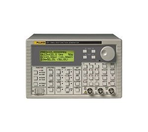
80/81 Function Pulse Generators
Ideal for both benchtop and ATE applications, the 80/81 family of 50 MHz waveform generators provides an unmatched combination of features and value
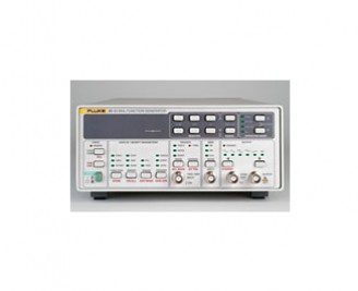
50 MHz Function/Pulse Generators
Ideal for both benchtop and ATE applications, the 80/81 family of 50 MHz waveform generators provides an unmatched combination of powerful operating features and great value. Each model generates sine, triangle, square, positive pulse, and negative pulse waveforms from 10 mHz to 50 MHz with up to 16 Vp-p amplitude into 50 Ohm. With many continuous and non-continuous modes from which to choose, Models 80/81 are ideal for a wide range of test applications.
- Model 81 pulse/function generator
- Model 80 function generator
- Powerful performance
- AM, FM, VCO, and phaselock/offset control modes
- Automated calibration
- Ideal for both benchtop and ATE applications
- HP 8116A emulation mode (81 only)
80 Function generator
Model 80 provides Sweep and FM. In addition, the 80 offers linear and logarithmic sweep functions and external FM. This makes the 80 an extremely versatile low-cost function generator.
81 Pulse/function generator
With programmable pulse period, width, and transition times combined with the function generator features common to the 80 family, the 81 provides an impressive set of capabilities for both analog and digital applications.
Store common setups
Both the 80 and 81 stores 30 complete front panel setups, allowing easy recall of test setups.
Remote operation
Model 80 and 81 include an IEEE-488.2 (GPIB) interface as standard.
Autocalibration optimizes performance
Each model has an autocalibration feature that allows the user to ensure maximum accuracy each time the unit is used.
Except as noted, specifications apply to Models 80 and 81 Specifications apply after a 20 minute warmup
Standard Waveforms |
|
| Standard Waveforms | Sine, triangle, square, positive and negative pulses, and (Model 80 only) dc |
Frequency |
|||||||
| Range | 10 mHz to 50 MHz | ||||||
| Resolution | 4 digits | ||||||
| Accuracy (Continuous Mode) |
|
Waveform Quality |
|||||||
| Harmonic Distortion (Sine) |
|
||||||
| Flatness |
|
||||||
| Triangle and Ramp Linearity | £5 MHz (10% to 90% of Amplitude): > 99% | ||||||
| Square Rise/Fall Time | (10% to 90% of Amplitude): < 6 ns | ||||||
| Square Aberrations | < 5% |
Pulse & Ramp (Model 81 Only) |
|||||||||||||
| Pulse Modes | Symmetrical pulse, positive pulse, negative pulse, and the complement to all pulse waveforms | ||||||||||||
| Pulse Period |
|
||||||||||||
| Pulse Width |
|
||||||||||||
| Ramp Period |
|
||||||||||||
| Ramp Width |
|
||||||||||||
| Transition Times |
|
Modulation |
|||||||
| AM and SCM |
|
||||||
| VCO |
|
||||||
| FM (Model 80 only) |
|
Amplitude |
|||||||||
| Range |
|
DC Offset |
|||||
| DC Offset | Offset and amplitude are independently adjustable within two windows: -800 mV to +800 mV -8V to +8V |
||||
| Range |
|
||||
| Resolution | 3 digits | ||||
| Accuracy (At 1 kHz) |
|
Main Output |
|
| Modes | Normal (on) or disabled (off) |
| Impedance | 50O ± 1% |
| Output Protection | Protected against continuous short to chassis ground |
Sync Output |
|
| Level (Into 50O) | 0 to 1V |
| Rise/Fall Time | < 3 ns |
Operating Modes |
|
| Operating Modes | Continuous, triggered, phaselock, start phase, and (Model 80 only) sweep |
Sweep Operation (80 Only) |
|||||
| Modes | Sweep may be continuous or triggered by any trigger mode | ||||
| Sweep Spacing | Linear and logarithmic | ||||
| Sweep Directions | Up, down, up-down, and down-up | ||||
| Sweep Range |
|
||||
| Sweep Rate |
|
||||
| Sweep Out |
|
Triggered Operation |
|||||||
| Modes | Single shot, gated, and burst | ||||||
| Sources | Manual (front panel key), internal trigger rate generator, and external signal input | ||||||
| Triggered | For each trigger, one output cycle is generated | ||||||
| Gated | Continuous waveform cycles are generated for the duration of the active portion of the trigger signal. Last cycle is always completed | ||||||
| Burst | Preset number of waveform cycles are generated by a trigger: 1 to 4,000 | ||||||
| Manual Trigger | Key provides trigger signal | ||||||
| Internal Trigger Rate Generator | 1 mHz to 50 kHz | ||||||
| External Input | Via Trig Input BNC | ||||||
| Impedance: | 10 kO ± 5% | ||||||
| Sensitivity: | 500 mVp-p | ||||||
| Max Input Voltage | ± 20V | ||||||
| Min Pulse Width | 20 ns | ||||||
| Max Frequency: | 50 MHz | ||||||
| Slope | Positive or negative going leading edges | ||||||
| Trigger Level: | Variable -10V to +10V | ||||||
| Start Phase of Triggered Waveform |
|
Model Name |
Description |
|---|---|
| Model 80 | 50 MHz Function Generator |
| Model 81 | 50 MHz Function/Pulse Generator |