- Unique traceability feature means no more re-calibrations
- Two high-stability models to meet your application, and fit your budget
- Up to 13 outputs, maximizing cost efficiency
- Central or remote monitoring, management and data collection, using the 910/910R Ethernet-port
- Two high-stability operating modes to suit your application
- Designed for portability too
- GPSView Software
Unique traceability feature means no more re-calibrations
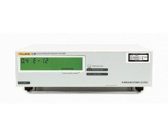
Off-air frequency standards have existed for several years. But until now, they all have had the same internal architecture (figure 1). The unit is, in effect, a "black box," with an antenna input and a frequency output. The local oscillator's control process (disciplining) is hidden from the user. Typically, users have used another frequency reference (for example, a rubidium standard), a timer/counter and a PC for logging the deviation between the "black box" and the frequency reference. The concept of traceability requires an unbroken chain of comparisons to international standards, on a continuing basis, where all comparisons produce documented results with stated uncertainty. Now, for the first time, a documenting frequency comparator and a very stable secondary standard are united within the same instrument together with the GPS receiver.The received GPS signal is measured continuously against the local oscillator. Phase and frequency deviation is stored internally and can at any time be transferred to any PC directly from the 910/910R or, via the optional Ethernet interface, from or to almost anywhere. Then by using the GPSView TM software supplied with every model, a printout of the traceability record can be obtained. The unbroken calibration history chain — day by day — is maintained in the non-volatile memory for several years, with the current 24-hour mean offset being displayed continuously on the front panel's LCD display.
Such unique traceability to primary standards means that the 910 and 910R GPS frequency standards never need to be away for re-calibration. Thanks to this design, the very high stability built-in rubidium or OCXO oscillator is continuously calibrated to the primary frequency standards in the US Naval Observatory and ultimately to UTC, in both operating modes, disciplined or manual hold-over.
Two high-stability models to meet your application, and fit your budget
Fluke Calibration offers two standard models in its GPS frequency standards range; the very-high stability 910R GPS frequency standard with its built-in rubidium atomic clock as the local oscillator, and the affordable 910 GPS frequency standard with its high stability local oven controlled crystal oscillator.
Up to 13 outputs, maximizing cost efficiency
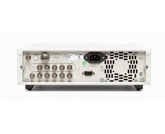
Both models come with one 5 MHz and five 10 MHz sinewave outputs as standard. A 1 pulse-per-second output is also included.If your application requires more outputs — for example, if several other instruments need to be supplied from the same frequency standard — option 70 allows you to mount five more 10 MHz outputs. Alternatively, option 72 allows you to expand your instrument to give five extra 2.048 MHz outputs, which is particularly useful in many telecoms applications. Option 73 provides five extra 13 MHz outputs, the standard frequency for GSM base station master clocks. Another variant on output configuration is offered through option 71, which gives the instrument an additional four sine wave outputs of 10 MHz, 5 MHz, 1 MHz and 0.1 Hz, plus a 0.1 MHz square wave output. And finally, option 75 allows you to define your own pulse frequency output.
Central or remote monitoring, management and data collection, using the 910/910R Ethernet-port.
The 910 and 910R GPS frequency standards can both be fitted with an optional Ethernet communication interface (option 76) which enables on-line access. Using the GPSView TM software supplied, it is possible to monitor both instrument and GPS status, or even collect calibration data, via the internet or any Local Area Network. With Ethernet interface connectivity, distances to which data can be transmitted become unlimited, unlike that of any standard GPIB or RS232 interface, thereby allowing the 910/910R GPS frequency standard to be monitored from practically anywhere. This means that the metrologist or lab technician no longer requires a 'floating' laptop PC to directly perform instrument management tasks, as this can now be achieved from any desktop PC, from any location inside or outside the calibration laboratory. It also allows data from multiple instruments to be simultaneously viewed in real time.
Two high-stability operating modes to suit your application
Most users prefer automatic adjustment (known as disciplining) of their frequency standard, to fully eliminate long-term frequency changes (aging). This disciplined mode is also the default mode in the 910 and 910R. As long as there is a valid satellite signal, the internal local oscillator is monitored and adjusted and the mean 24-hour frequency offset is always virtually zero. However, in this mode, the inherent short-to-medium term stability of all local oscillators, except rubidium, is compromised. This is true for all GPS frequency references. The received GPS signal has relatively large short-term frequency variations, due to variations in atmospheric conditions. This means that when using the received GPS signal for disciplining the 910 (OXCO), the stability is reduced a little for averaging times of 100 s to 1000 s. In this mode, the frequency deviation between the internal timebase oscillator and the received GPS-signal is used to continuously adjust the oscillator (disciplining). The resulting frequency offset and adjustment data is stored in non-volatile memory every 24 hours, to enable printout of the traceability record. The actual frequency offset (24-hour mean value) is calculated and displayed on the front panel.Some applications demand superior short-medium term stability, especially for jitter and wander measurements in digital telecommunication networks.
The unique Manual Hold-Over Mode makes it possible to switch over temporarily from Disciplined to Hold-Over Mode during the actual measurement, thereby achieving a superior frequency accuracy at the start of the measurement and a superior stability through the measurement. Here, the internal oscillator is not adjusted. This mode is normally automatically entered when there is no usable received GPS-signal. This mode can also be selected manually by activating the Manual Hold-Over Key. If Manual Hold-Over is set together with a valid received GPS signal, the actual frequency offset is calculated, displayed and stored in non-volatile memory every 24 hours.
For the ultra-stable rubidium oscillator in the 910R, there is no measurable difference between the stability in Disciplined and Hold-Over mode, for averaging times up to 1000 s.
Designed for portability too
When using Manual Hold-Over Mode, the 910 or 910R act as a stand-alone OCXO or rubidium frequency standard. This means that one typical drawback of a GPS receiver, lack of portability, is eliminated. A typical GPS receiver needs hours to lock after a change of location, whereas the 910 and 910R are up and running after just ten minutes.
GPSView Software
GPSView is a Windows 95/98/ 2000/NT program that communicates with the GPS-controlled frequency standard. Its main purpose is to provide a traceable calibration document based on the 24 hour frequency offset values, internally stored in the non-volatile memory of model 910/910R (figure 3).It is only necessary to download data to a PC to the 910/910R once every second year to obtain an unbroken traceability chain since first use. For performance analysis over a shorter period and for short-term phase variation, data can be obtained over the latest forty-day period.
From GPSView, the user can control the operating mode (Disciplined or Hold-Over), and lock the front panel to prevent unintended change via the Manual Hold-Over Key. The user can also set the optional pulse output frequency and duty cycle.