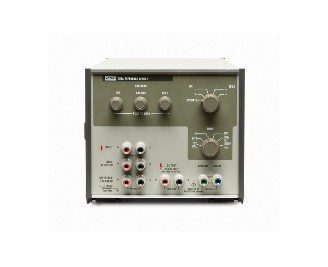
Fluke 752A Reference Divider
The 752A reference dividers are precision 10:1 and 100:1 dividers designed primarily for comparing direct voltage levels of various sources
Setting the standard for ratio accuracy and ease of use
The 752A reference dividers are precision 10:1 and 100:1 dividers designed primarily for comparing direct voltage levels of various sources to a 10V voltage reference standard like a 732B.
Internal switching allows calibration of the 100 mV, 1V, 10V, 100V and 1000V ranges of a voltage calibrator with a 10V standard like the 732B without the need to change connections.
A self-calibration procedure allows you to compensate for long-term changes in value of the divider resistors by switching their positions in various Wheatstone bridge configurations.
- 10:1 and 100:1 divider outputs
- Output uncertainty 0.2 ppm and 0.5 ppm
- Built-in calibration bridge
- Dynamic Resistor Matching™
- System switching for ease of use
- Operating modes
The 752A Reference Divider sets the standard for ratio accuracy and ease of use. It offers two divider outputs, 10:1 and 100:1 with output uncertainties of less than 0.2 ppm and 0.5 ppm respectively.
Before each use, 752A reference dividers are easily calibrated with only a stable source and a null detector. The entire procedure takes only five minutes and does not require external standards.
The calibration procedure compensates for long term changes in value of the divider resistors. The upper leg of the divider is configured into three equal groups, which, when placed in parallel, form a resistor of equal value to the output resistor. These two resistors form one half of a Wheatstone bridge. The other half is composed of two calibration resistors whose positions can be interchanged in the circuit. This interchange allows correction for any difference in the values of the calibration resistors through use of the BALANCE knob on the front panel. The upper leg resistors are then matched to the output resistor with the 10:1 or 100:1 potentiometers respectively.
Operating modes
In the stand-alone divider mode, input to the divider is applied to the INPUT terminals and is switched by the MODE switch to either the 10:1 or the 100:1 position. Output from the divider is then available at the OUTPUT terminals.
When the 752A reference dividers are augmented with a 10V reference source and a null detector, the resulting system becomes a 5-decade cardinal point voltage calibrator with facilities for comparing input voltages of 1000V, 100V, 10V, 1V and 0.1V to the 10V reference. In this mode, the voltage source to be calibrated is connected to the 752A input terminals and the MODE switch reconfigures the system for each of the ranges with no manual lead changing necessary.
When the MODE switch is turned to the 752 CAL position, the 752A divider resistors are switched to form a bridge circuit with the two additional calibration resistors. Bridge excitation is supplied from the voltage source (set for an output of 20V) connected to the input terminals and the null detector is switched across the bridge to measure bridge balance.
Division Ratio |
|||
| Division Ratio 10:1 ±0.2 ppm |
|
||
| Division Ratio 100:1 ±0.5 ppm |
|
General Specifications * |
|||||||||||||||||||
| Ratio Ranges |
|
||||||||||||||||||
| Ratio Uncertainty |
|
||||||||||||||||||
| Temperature Coefficient |
|
||||||||||||||||||
| Input Resistance |
|
||||||||||||||||||
| Maximum Input Voltage |
|
||||||||||||||||||
| Power Coefficient |
|
||||||||||||||||||
| Temperature |
|
||||||||||||||||||
| Relative Humidity |
|
||||||||||||||||||
| Altitude |
|
||||||||||||||||||
| Vibration |
|
||||||||||||||||||
| Safety |
|
||||||||||||||||||
| Calibration Documentation | Statement of calibration practices included; performance check optional | ||||||||||||||||||
| Size |
|
||||||||||||||||||
| Weight |
|
*Specifications apply for the lifetime of the instrument over the temperature range of 18°C to 28°C.
**Null accuracy refers to the required accuracy of the null detector reading during self-calibration.
Accessory |
Description |
|---|---|
| 5440A-7002 | Low Thermal Copper EMF Plug-In Cables, Banana Connectors |
| 5440A-7003 | Low Thermal Copper EMF Plug-In Cables, Spade Connectors |